
Now let’s see what the PQ² diagram of a press is and why it is essential to understand how to correctly size the mould.
What is the PQ² diagram?
The PQ² diagram of the press graphically expresses how the injection unit, that is the hydraulic system consisting of accumulators and hydraulic cylinder that manages the movement of the injection plunger, can deliver energy within those few tens of milliseconds of the second phase during which the mould cavity is filled.
In this very short period of time, the alloy in the liquid state is pushed through the casting gates at a speed of a few tens of meters per second to complete the filling before it cools too much and then it is immediately compressed before the third stage of intensification takes place. In this matter of milliseconds, the casting is then shaped and most of its quality defined. This is a phenomenon that occurs in very short times and with very high dynamics and it is, therefore, essential to understand if the injection unit of the press can carry out this operation correctly: just as on a car, performance depends on the torque curve of engine power, the performance of a press during the second injection phase depends on the PQ² diagram of the injection system.
What happens during the metal injection?
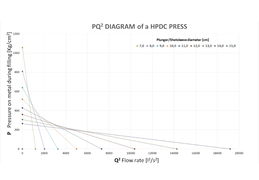
In practice, the PQ² diagram of the press expresses the relationship that binds the pressure P, that the machine can exert on the liquid metal through the plunger and the flow rate Q of the metal, and therefore the speed, which arises during the filling in the 2nd phase. Going into detail, the machine’s injection system can deliver a certain amount of energy and transfer it to the liquid metal in the form of speed and/or pressure. This correlation is inverse: by increasing the speed (flow rate), the machine can impart less pressure to the metal and vice versa. This link follows a quadratic law, hence the term PQ², which can be represented for convenience as a straight line in a graph in which the squared flow rate values are reported in the abscissa, while the pressures are reported in the ordinate.
The machine is, therefore, able to reach its maximum injection flow rate (speed) in ideal conditions when the plunger offers no resistance (pressure) to the advancement, which are known as “dry” conditions without metal in the shot sleeve. This flow rate, identified from the point at the bottom right, depends on various design choices made by the press manufacturer including the hydraulic scheme, the diameters of the hydraulic injection cylinder and the plunger/shot sleeve adopted, the sizing and pressure of the 2nd phase accumulators, the type of valve mounted on the machine and its opening ratio. Not all machines, therefore, have the same characteristics and offer the same performance.
At maximum speed, the machine delivers its power only in terms of speed and therefore the pressure it can impart to the metal is zero: it is a purely ideal situation and can only be found in a “test” executed in the laboratory as in the actual process there will always be liquid metal which opposes resistance to advancement.
In reality, therefore, the machine will always work at an intermediate point where it develops sufficient pressure to make the plunger move (and consequently overcome the resistance offered by the liquid metal) with a speed lower than the maximum and regulated by the partialization of the opening of a hydraulic valve.
What happens when the diameter of the plunger mounted on the press changes?
By increasing the diameter of the shot sleeve, the cross-section front surface of the plunger increases and therefore Q also increases by developing higher flow rates, but at the same time, the pressure capable of overcoming the friction of the fluid metal decreases as well the capacity to accelerate it and then compress it in the mould.
As the filling proceeds, the resistance offered by the metal entering the mould increases until the cavity is almost full.
When the cavity is full and the piston is forced to stop, what happens?
The pressure that the machine can exert on the liquid metal is maximum when the plunger is stopped (at the end of filling), is called “2nd phase static pressure” and is represented by the point at the top left in the PQ² diagram: all the injection force is developed in terms of pressure as the speed is zero. This point depends solely on the configuration of the injection system of the press: pre-charge pressure in the accumulators, the diameter of the hydraulic injection cylinder and the diameter of the plunger mounted. As the plunger diameter decreases, the 2nd phase static pressure increases and consequently the degree of compaction that the metal undergoes in the mould, regardless of the intensification. This pressure, although it does not reach particularly high pressures (usually it is in the order of 300-500 Kg/cm 2, against 500-1000 of the intensification) is particularly effective in compacting the metal in the mould as it acts on metal still completely liquid, before the casting gates solidify, increasing thus the compactness of the casting.
Consequentially, the choice of an incorrect plunger diameter leads, if too small, to the formation of flashes on the parting lines since the clamping force of the machine can be exceeded by the peak of pressure or, on the opposite, to insufficient compaction of the metal which can not be solved even by pushing the 3rd phase of intensification can occur.
Conclusion: the PQ² diagram
It is therefore conceivable, in a comparison with the car, that the diameter of the plunger/shot sleeve mounted on the press is the equivalent of the gear engaged: small diameters are equivalent to low gears, which are suitable for climbing steep slopes at low speed and give high accelerations by running the engine at high revs. On the other hand, large diameters are equivalent to high gears that are suitable when there is a need to develop high speeds (capacities) at low rpm but they struggle when you find a slope or you have to accelerate. The engine is the same, it changes the way power is transmitted to the ground and made available. The problem is that, while in a car we can change gears according to the need of the path, the choice of the diameter of the piston of a mould must be made a priori and therefore it is essential to carry out an in-depth evaluation to find the best compromise between agility and speed.
In a future article, we will instead see the meaning of the PQ² diagram of the mould and superimpose it on the press diagram to perform an optimal sizing of the casting gates.