
In the previous article we analyzed the PQ2 diagram of the injection shot-end. We understood that it is necessary to predict how the machine can deliver the energy to fill the mold cavity with metal. Now, by drawing the PQ2 curve of the mold, we will see how the metal uses the energy delivered by the machine. We will also try to understand the main factors that influence the mold curve and how it interacts with that of the press.
From a functional point of view, the mold is the user of the energy supplied by the hydraulic system of the press, which is transmitted to the liquid metal through the injection plunger. A user, however, has a radically different behavior from that of the energy provider. While the press, as the plunger speed increases, can overcome lower and lower pressures, the user behaves in the opposite way: as the speed increases, it offers an increasingly higher resistance in the form of a gradually increasing counter pressure. We can easily experience this by spraying water with a syringe: the more we want to spray it quickly and far, the more we have to force our thumbs on the piston.
The Bernoulli formula
How is it possible to determine the proper pressure to exert on a fluid to make it pass through a hole with a certain speed? The calculation is highly complex and depends on many factors, and the problem has no simple solution. However, it is possible to make some simplifications and use relatively uncomplicated formulas borrowed from plumbing. Going back in time to the eighteenth century, a physicist named Daniel Bernoulli devoted part of his life to the study of the behavior of water in pipes and theorized their behavior, simplifying it in a formula that is still used today in the most disparate fields: hydroelectric power plants as well as in fountains and, indeed, die casting.
Without going into the mathematical detail of what Bernoulli claims, we can say in a nutshell that the pressure that must be exerted to make a fluid (in our case, the liquid alloy) flow through a slot (gates) with a certain speed (the speed at the gates) is proportional to the square of the fluid velocity. That is, to double the velocity of the fluid, we have to quadruple the applied pressure.
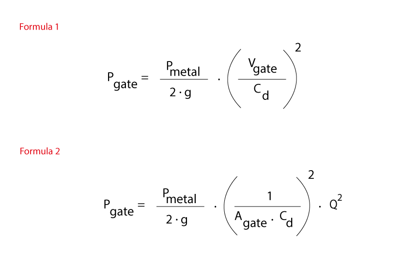
Formula n° 1
Returning to the automotive comparison, we immediately realize the same thing that happens when driving a vehicle: doubling the speed means consuming much more than double. To reach high speed, we need to deliver very high power.
Let’s think of a mold that has a specific gate area (Agate): given that liquid aluminum is not compressible, we can say with certainty that the flow rate of metal (Q) that passes through the gates is given by the product of the velocity (Vgate) of the metal to the gate multiplied by the gate cross-section Agate. It follows that the speed of the metal V is given by the ratio between the flow rate Q and the gate area A. So we can say that the Bernoulli equation, rewritten and simplified for die casting, states that the pressure Pgate that the plunger must exert on the metal in the shotsleeve to push it with a certain flow rate through the casting gatings is proportional to the square of the flow rate Q and inversely proportional to the square of the gate cross-section Agate.
Formula n°2
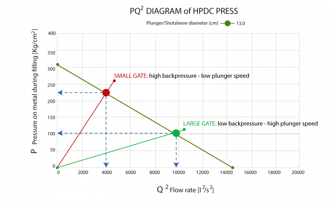
This means that the correlation between the pressure exerted on the metal and its flow rate is a quadratic law and, as for the PQ2 of the machine, we can draw it as a straight line on the PQ2 diagram. In fact, these are exactly the same pressures P and flow rate Q that the machine diagram expresses. In this case, however, the straight line will have an increasing slope and will intersect with the decreasing one of the machine.
The correlation between the gate area and pressure is quadratic but inverse: i.e., by increasing the gating section, the straight-line slope is reduced, i.e., to reach the same flow rate (or speed), the machine makes less effort because it must exert less pressure. In a nutshell, by doubling the section of the gating, it is possible to reduce the pressure to a quarter to maintain the same flow rate. It follows that if the casting gatings are too undersized for the needs of the mold, the machine could also have difficulty reaching the desired filling speed.
Actually, the slope of the straight line of the mold depends not only on the area of the gate but also on the density of the metal considered: to push a metal with a high density (Zamak, for example, which has a density rmetal =6.2 kg/dm3) requires much more pressure than Magnesium (1.6 kg/dm3) by virtue of the fact that the ratio between their densities is approximately 4: 1. On the other hand, we quickly understand how accelerating a fully-loaded car requires much more force than accelerating the same vehicle when it is empty.
The Discharge Coefficient
Density is not the only factor that is taken into account in the Bernoulli formula. There is another parameter called “Discharge Coefficient” Cd: it’s a value between 0 and 1 (usually in the range 0.55-0.7), which indicates the “efficiency” of the hydraulic system namely, and quantifies the energy losses caused by fluid friction and by an inaccurate design of the runners. Poorly designed runners, with abrupt changes of direction, suboptimal cross-sections, and too high roughness, cause significant energy losses that hinder the flow of the metal.
Returning to the automotive comparison, it is intuitive that driving a narrow, winding, and potholed road at high speed is more tiring than driving a 4-lane motorway. Hence, the need to thoroughly optimize the design of the runners, with the CastleRUN module, for example, to avoid that part of the energy supplied by the machine being lost unnecessarily and is not correctly transferred to the liquid metal.
In conclusion
Concluding the discussion, we can trace both the straight line of the machine and that of the mold on the same PQ2 diagram and see where they intersect. That is, where the pressure delivered by the machine on the metal is equivalent to the counter pressure that the gating exerts. At this point, the delivered force is equal to the resistant force, and we have identified the “maximum speed” of the vehicle: even if we press the accelerator further, the car does not increase its speed. It is therefore evident that this type of analysis makes it possible to understand whether a specific mold, mounted on a particular machine that uses a specific plunger diameter, can work by moving a flow rate of metal Q (or, equivalently, a plunger speed) sufficient to fill the mold correctly, and if the gates are appropriately sized.
Consequently, the next step will consist of identifying on the PQ2 diagram an optimal work area for the production of a particular component and then putting all information together to verify that the choices made in the sizing of the gate, the plunger, and the machine are suitable.